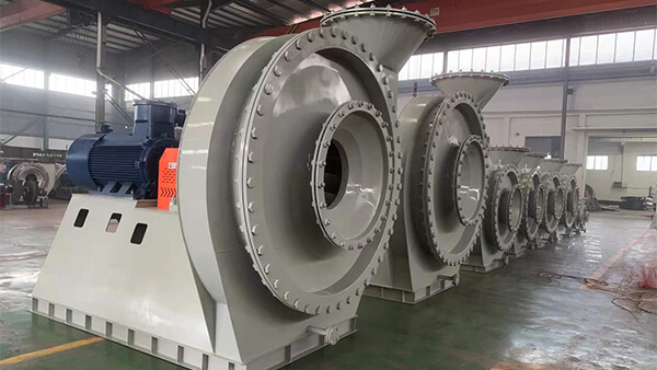
When engineers talk about blower efficiency losses, the impeller usually gets blamed first — blade profile, inlet incidence angle, blade count. The volute, meanwhile, tends to get treated as a foregone conclusion: gas leaves the impeller, swirls around the volute, and exits — nothing worth digging into. But from a fluid dynamics standpoint, the flow structure inside a volute is genuinely complex, and it changes in a predictable, systematic way depending on how far the blower is running from its design flow point. Understanding that pattern is really the starting point for any serious attempt at reducing losses and noise.
The Two Velocity Components That Decide What Happens Inside the Volute
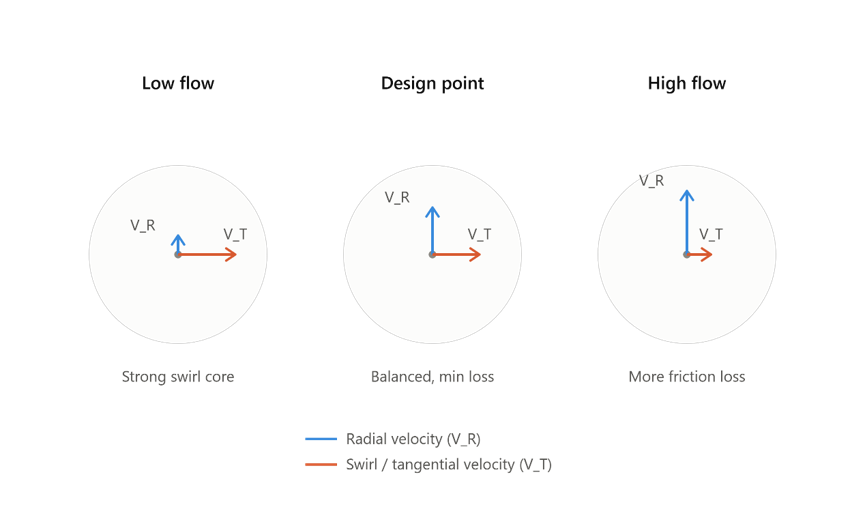
Flow leaving the impeller can be split into two components: a radial component (moving outward along the radius) and a tangential component (following the impeller’s rotation). The relative balance between these two components determines exactly how the gas behaves once it enters the volute.
At the design flow point, this balance is “correct” — the flow spirals through the volute in a smooth diffusion process, circumferential static pressure stays fairly uniform, and the volute barely disturbs the pressure recovery already achieved. Move off that design point, though, and the balance breaks down. At higher-than-design flow, the radial velocity component grows relative to what the volute geometry was sized for, so the actual flow velocity through the volute ends up exceeding what the diffusion process needs — which partially destroys the pressure rise already built up in the impeller and adds extra loss. At lower-than-design flow, it’s the opposite: radial velocity drops off, the tangential swirl component dominates, and a strong vortex motion develops inside the volute. That swirl energy eventually dissipates through internal shear and wall friction — which is loss just the same, just a different mechanism.
In other words, a volute is never a generic duct. It’s a geometry optimized for one specific flow point — which is exactly why efficiency tends to drop off more sharply than people expect once a blower is pushed away from its design condition.
The Forced Vortex at the Volute Centre — An Easy-to-Miss Loss Source
Inside a volute cross section, flow is never uniformly distributed. Gas entering near the tongue, at a smaller radius, tends to occupy the centre of the cross section first, while gas entering further downstream at a larger radius wraps around it — layered vortex tubes, essentially. Near the design flow point, this structure tends toward what’s called a forced vortex: the centre region behaves almost like solid-body rotation, while the outer region retains a stronger tangential velocity.
The problem is that this forced-vortex centre carries a real total pressure loss and a real static pressure drop with it — the stronger the tangential velocity, the deeper the low-pressure core and the greater the shear dissipation. The further a blower’s actual flow deviates from its design point (in either direction), the more pronounced this centre-vortex loss tends to become — which is exactly why volute efficiency correlates so strongly with how far off-design the blower is actually operating.
Breaking Volute Losses Into Three Components
Rather than describing volute performance as one vague “efficiency” number, engineers typically split the loss into distinct components, each tied to a different physical mechanism:
Friction losses — governed by the volute’s hydraulic diameter, the actual flow path length, and internal wall roughness; fundamentally the same mechanism as ordinary duct friction.
Meridional (radial) velocity dump losses — if the radial velocity component leaving the impeller isn’t effectively recovered inside the volute, that kinetic energy is essentially wasted. This tends to be the dominant loss term at low flow.
Tangential velocity dump losses — if tangential velocity at the volute outlet is lower than at the inlet, the flow is diffusing, and the loss behaves like a sudden-expansion mixing process. If tangential velocity is accelerating instead, this loss is close to negligible. This is also why an inlet-converging, outlet-expanding volute profile tends to outperform a constant-cross-section design — it keeps tangential velocity in an accelerating trend through the passage rather than letting it suddenly diffuse.
Exit cone diffuser losses — loss coefficients rise sharply once the cone’s total opening angle exceeds roughly 10°; keeping the angle smaller generally keeps this loss coefficient low.
Two Underrated Design Variables: Tongue Clearance and Cross-Section Geometry
The clearance between the volute tongue and the impeller outer edge has a direct effect on how uniform the circumferential pressure distribution ends up being. Too small a clearance intensifies pressure pulsation and flow interference right at the tongue; a moderately larger clearance gives local distortion near the tongue more room to smooth out. But clearance can’t be increased indefinitely either — too large, and high-pressure gas risks flowing back toward the impeller outlet, which brings its own losses and noise.
Cross-section shape and its radial location also matter more than they’re often given credit for. Volutes with the same cross-section area variation but positioned closer to the rotational centre tend to show noticeably higher losses. Circular cross sections have a small edge over rectangular ones simply because a smaller wetted perimeter means less friction loss — but that doesn’t mean rectangular sections automatically lose more to flow turning through 90° corners. In practice, the throughflow velocity component is usually much larger than the swirl component, so the flow tends to approach the corner tangentially rather than actually executing a sharp 90° turn.
The Bottom Line
Vortices and separation inside a volute are fundamentally the product of interaction between the impeller’s outlet flow conditions and the volute’s geometry — and that interaction shifts systematically with operating flow. This is exactly why optimizing the impeller alone, or the volute profile alone, rarely gets overall efficiency and noise performance to where they need to be. A more solid approach couples impeller outlet velocity distribution with internal volute flow as one system, using simulation to iterate on tongue clearance, diffusion angle, and cross-section shape together — rather than defaulting to a generic empirical formula.
In developing volute profiles, Yutong EP Blower follows this same approach — treating the impeller outlet velocity triangle and the internal volute flow field as one coupled system to evaluate and refine, with the goal of catching and resolving as much of this loss and noise potential as possible at the design stage.