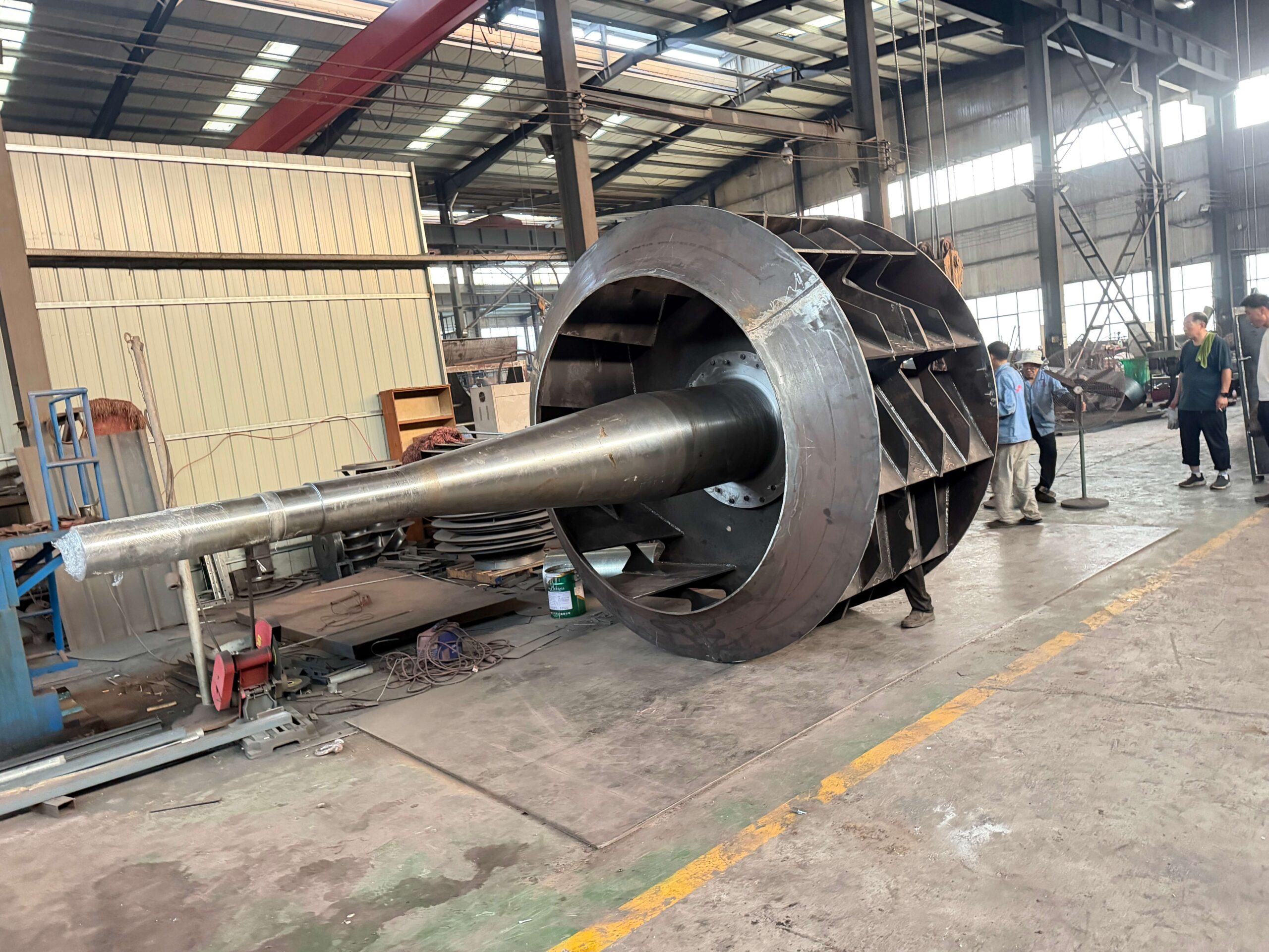
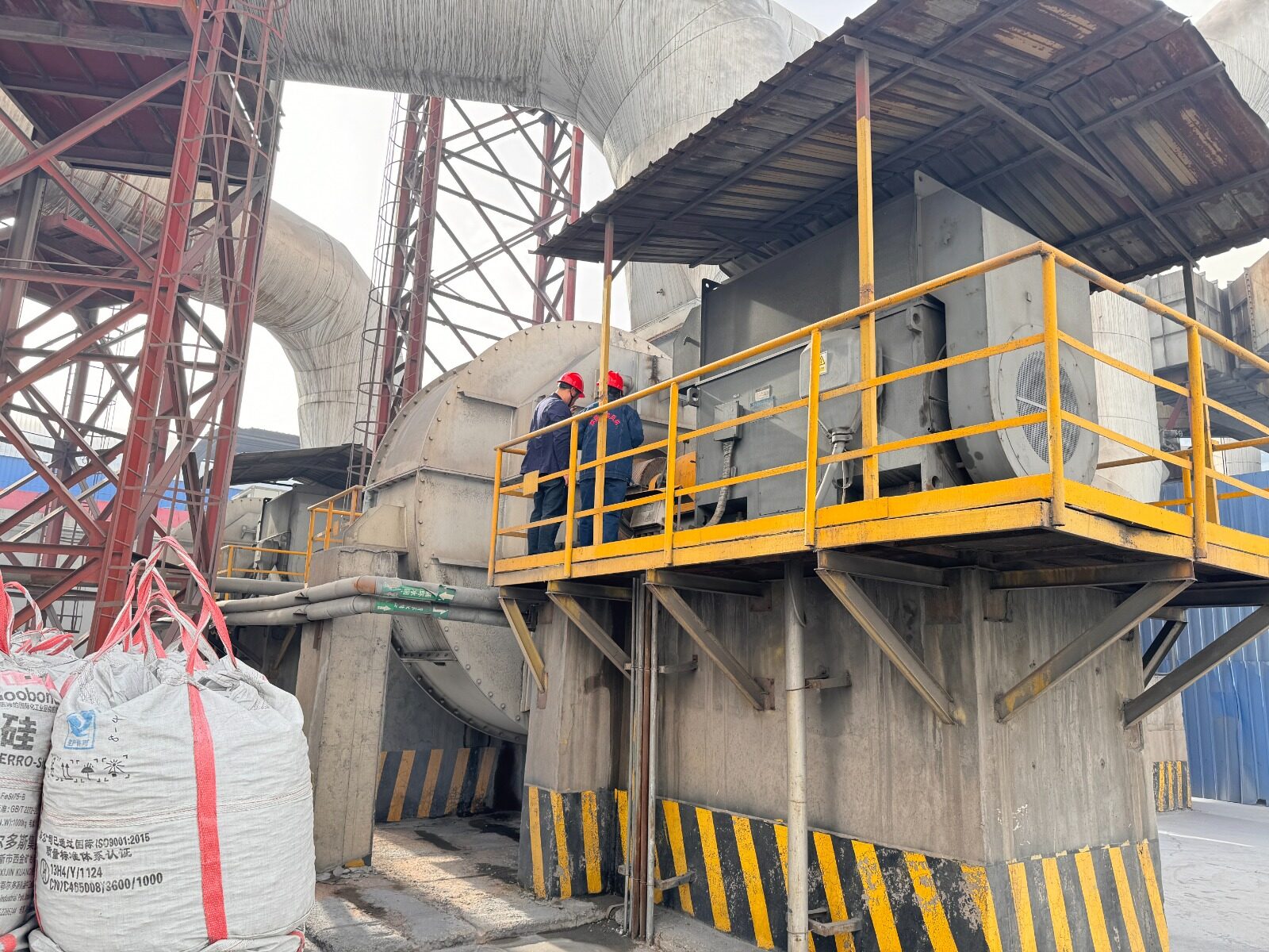
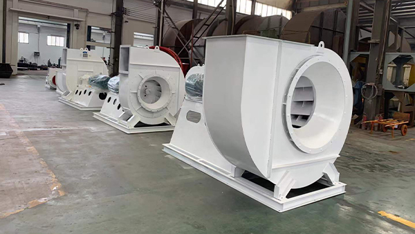
There’s a specific kind of gas stream that separates a blower built for general industry from one built to survive underground. Crushing circuits, roasting and smelting off-gas, ore-handling ventilation — these aren’t just dusty. The particulate is hard, angular, and moving at velocity, and it treats a standard impeller like sandpaper treats soft pine. We’re currently building and preparing to ship a rotor sized for exactly that environment: a double-inlet, Arrangement F centrifugal blower rotor at 2.2 meters, destined for a mining application in Latin America. This is what goes into it, and why the specification looks the way it does.
Why Standard Blowers Fail in Mining Duty — and Why This One Doesn’t
Abrasive dust from ore crushing and smelting off-gas doesn’t announce itself gradually. A blower undersized for the abrasion load doesn’t degrade — it fails. Impeller blades thin out at the leading edge, the resulting imbalance drives vibration well past acceptable limits, and what started as gradual wear becomes a bearing failure or a shaft crack. For a mine site or a smelter, that’s not a maintenance line item — it’s a production line stopped, and depending on the process, a very expensive one.
The rotor we’re building addresses that at the structural level, not just the surface level. It’s a double-inlet (double-suction) design, drawing gas symmetrically from both sides of the impeller. That configuration does two things simultaneously: it delivers the massive airflow volume a large-scale mining ventilation or process gas system demands without oversizing the impeller diameter beyond what’s practical to fabricate and balance, and — just as important — it balances axial thrust across the rotor by design, rather than relying on a single-inlet geometry that pushes all axial load in one direction onto the bearing system.
Why Standard Blowers Fail in Mining Duty — and Why This One Doesn’t
At 2.2 meters and the torque loads this duty class generates, the single biggest threat to long-term reliability isn’t the impeller wearing down — it’s the shaft flexing under load. Any centrifugal machine transmitting high torque through an overhung or single-support shaft configuration is fighting deflection with every rotation. Over months of continuous operation, that deflection shows up as bearing wear, seal degradation, and vibration trending in the wrong direction — degradation that accelerates rather than plateaus.
We build this class of rotor on Arrangement F — a dual-support drive configuration, with bearings positioned on both sides of the impeller rather than cantilevered off one end. Mechanically, this converts the shaft from a cantilever beam problem into a simply-supported beam problem, which is a fundamentally stiffer condition under the same load. The practical result: shaft deflection stays within tolerance across the full operating envelope, bearing loads stay predictable rather than escalating, and the rotor holds its dynamic balance over years of continuous duty instead of months. For a mine or smelter running the blower as critical-path equipment, that’s the difference between a scheduled overhaul and an unscheduled one.
Built for Abrasion, Verified Before It Ever Leaves the Shop
Structural stiffness solves the deflection problem. It doesn’t solve abrasion. That’s addressed separately, at the material and surface level. The rotor body is fabricated from heavy-gauge steel plate, welded rather than cast — a construction approach that allows us to size wall thickness specifically for the abrasion allowance the application requires, rather than accepting whatever thickness a casting pattern happens to produce.
Where the duty calls for it, we apply EPDM rubber lining or tungsten carbide wear coating on the surfaces taking the direct impingement — tungsten carbide where hardness against high-velocity particulate impact is the priority, EPDM where resilience against a broader abrasive-slurry-type environment is the better fit. Which one makes sense depends on the specific ore, the particle size distribution, and the gas velocity at that stage of the process — not a default answer.
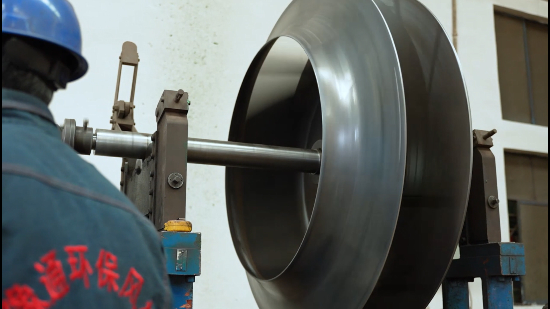
None of that matters if the rotor doesn’t run true. Before this unit ships, it goes through full dynamic balancing as an assembled rotor — impeller and shaft together, at operating speed, not estimated from component-level tolerances. The target is zero-vibration performance at the coupling and bearing housings across the operating speed range. At this mass and diameter, a residual imbalance that would be a rounding error on a small blower becomes a significant cyclic force here — which is exactly why this step doesn’t get compressed or skipped, regardless of schedule pressure.
Built to Spec, Built to Last — and Built to Replace What’s Already Failing
Large mining sites and EPC contractors across Chile, Peru, Brazil, and Mexico are running process gas and ventilation systems that were specified years ago, often for a throughput or ore composition that has since changed. If a blower on your site is showing rising vibration trends, more frequent bearing changes, or impeller wear you’re chasing rather than getting ahead of, that’s usually not a fleet-wide problem — it’s a specification mismatch that a retrofit or direct replacement resolves.
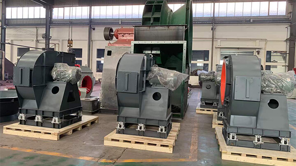
[P] We engineer both new rotor packages and drop-in replacements sized to the actual duty — airflow, abrasion load, and mechanical arrangement matched to your process, not a generic catalog selection. If you’re specifying a new dust or process gas system, or looking to replace a unit that’s underperforming its intended service life, our engineering team can work directly from your process data. Contact Yutong EP Blower to start that conversation.