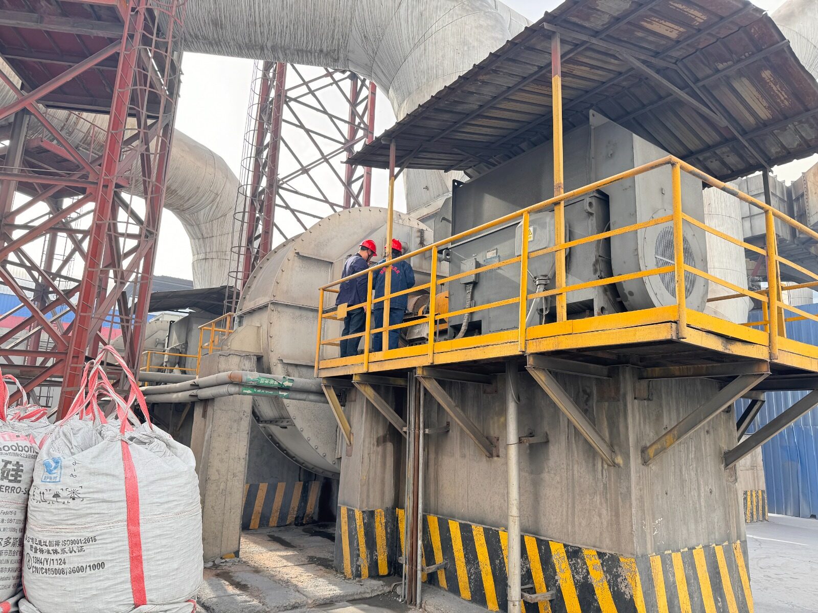
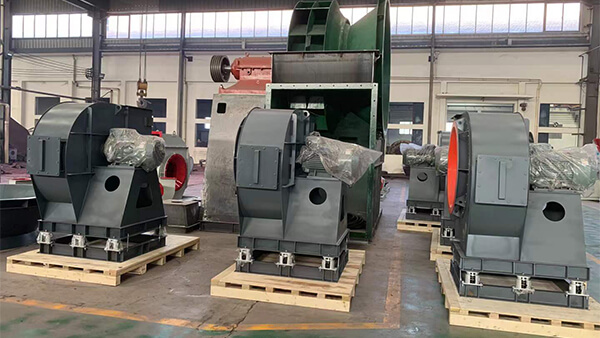
Blast furnace dust removal is one of those systems that runs around the clock without much attention — until the electricity bill or the maintenance log makes it impossible to ignore. In steelmaking, hot metal and slag reacting with moisture and air generate large volumes of dust-laden gas that has to be pulled out continuously to protect workers and meet environmental requirements. That means the dust removal blower almost never gets to shut down. For plants still running these blowers at fixed speed, the retrofit path to a high-voltage variable frequency drive (VFD) is one of the more reliably profitable upgrades available — not just on paper, but in measured results from actual installations.
Why Fixed-Speed Dust Removal Blowers Waste So Much Energy?
The traditional way to control airflow on a large industrial blower without changing motor speed is to throttle a damper and rely on a hydraulic coupling to adjust output. The motor itself just runs at line frequency continuously, regardless of whether the process actually needs full airflow at that moment. This approach has two well-known problems.
First, it’s wasteful — throttling a damper doesn’t reduce the energy the motor consumes nearly as much as it reduces the airflow delivered, so a large share of the motor’s power output is essentially discarded as artificial resistance. Second, hydraulic couplings are a mechanical speed-control method, and mechanical components wear. Plants running these systems typically report higher failure rates and correspondingly heavier maintenance workloads compared with electronic speed control.
How a High-Voltage VFD Retrofit Actually Works?
For blowers running on medium-voltage supply (commonly 10kV in Chinese steel plants), the retrofit isn’t a simple off-the-shelf drive — it requires a cascaded multilevel architecture. A phase-shifting transformer feeds a series of independent power cells, each supplying its own isolated three-phase 50Hz output; because each cell’s secondary winding is phase-shifted relative to the others, the harmonic content on the input side drops sharply — a meaningful benefit given how sensitive plant electrical systems are to harmonic pollution.
Each power cell itself is built around a three-phase bridge rectifier, filter capacitors, and an IGBT H-bridge inverter, with the cells connected in series so that at 10kV, the total output voltage is effectively built up by stacking multiple cell outputs — not unlike how battery cells stack in series to reach a target voltage.
On the control side, most retrofits of this kind use open-loop constant voltage-to-frequency ratio control (U/f control) rather than vector control. U/f control is simpler in both hardware and software, generally more cost-effective, and adequate for blower loads where precise torque control isn’t critical — which is why it remains the practical choice for this application even though it’s a less sophisticated method than full vector control.
Reliability is handled through a bypass arrangement rather than by trusting the VFD alone. The original water-resistance starting cabinet and hydraulic coupling are wired as an automatic, mutually interlocked bypass path. Under normal conditions, the water-resistance cabinet is bypassed and the motor starts through the VFD; if the VFD ever faults, the system isolates the drive’s input and output switches, falls back to the power-frequency path, brings the water-resistance cabinet back in to limit starting current, and starts the motor conventionally. The process is not seamless, but it means a VFD failure doesn’t take the dust removal system offline — which matters enormously for a piece of equipment tied directly to worker safety and environmental compliance.
The Energy-Saving Math Behind Speed Control
The reason VFD retrofits pay for themselves so reliably comes down to a basic relationship in centrifugal machinery: airflow scales roughly in direct proportion to motor speed, while power consumption scales with the cube of motor speed. Cut speed by 20%, and airflow drops by about 20% — but power consumption can drop by nearly 50%. That cubic relationship is what makes speed control fundamentally more efficient than throttling a damper at full speed: a damper wastes energy as resistance, while a VFD avoids generating that unneeded energy in the first place.
VFD Energy Savings Calculator
Based on Centrifugal Fan Affinity Laws
Estimated Results:
New Power Consumption: 1024 kW
Power Saved: 976 kW
Monthly Cost Savings: $491904
*Based on 24 hours/day, 30 days/month.
A Real Retrofit, With Real Numbers
One documented case involved a blast furnace dust removal blower with a design airflow of 900,000 m³/h, driven by a 2000kW, 10kV motor rated at 997 rpm. Before the retrofit, the blower ran at fixed frequency with the damper open to only 80%, motor speed sitting around 920 rpm, drawing roughly 112A and consuming about 1,157,000 kWh per month.
After the VFD retrofit, the damper was opened fully to 100% and the blower’s actual speed was controlled electronically — dropping to roughly 747 rpm, running at a variable 40Hz or 25Hz depending on process demand, with current in the 65–99A range. Monthly consumption fell to about 843,500 kWh — a reduction of roughly 316,600 kWh per month. At the plant’s electricity rate of ¥0.7 per kWh, that worked out to about ¥217,500 saved per month, or roughly ¥2.61 million per year, based on continuous 24-hour, 31-day operation.
Bearing vibration readings on both the front and rear bearings also dropped noticeably after the retrofit — a secondary but meaningful indicator, since lower vibration generally correlates with less mechanical wear, longer bearing life, and longer intervals between overhauls.
Matching Blower Speed to Actual Process Demand
The efficiency gain compounds further once speed is tied to actual production activity rather than run continuously at one setting. In this plant’s blast furnace operation, each furnace has two taphole outlets, with an average of about two hours needed per taphole — roughly 80 minutes of active tapping followed by about a 40-minute interval between taps. Running the blower at 40Hz during active tapping (when dust and fume generation is highest) and dropping it to 25Hz during the interval between taps let the plant capture savings that a single fixed reduced speed couldn’t achieve.
In this specific comparison, motor current during tapping ran around 99A versus about 65A during the interval period; converting that current differential into annual energy and cost terms using the plant’s electricity rate showed roughly 130,000 kWh and close to ¥920,000 in additional yearly savings from this demand-matching strategy alone — on top of the baseline retrofit savings described above.
Benefits Beyond the Electricity Bill
The energy savings tend to dominate the payback calculation, but plant staff reported a few other changes worth noting. With the damper running fully open under VFD control rather than partially throttled, both blower noise and duct noise dropped noticeably, which operators specifically flagged as an improvement to the working environment.
Speed control also simplified day-to-day operation — adjusting output now just means adjusting frequency electronically, rather than manually managing damper position and hydraulic coupling slip. And with less throttling stress and lower vibration, wear on bearings and other rotating components slowed, which translated into longer intervals between inspections and lower overall maintenance cost.
What This Means for Blower Selection and Retrofit Planning?
Cases like this are a useful reminder that a blower’s efficiency isn’t fixed at the point of manufacture — how it’s controlled in the field matters just as much as impeller design or casing efficiency. For plants still running large industrial blowers on fixed-frequency power with damper throttling, a high-voltage VFD retrofit is one of the more predictable ways to cut both energy cost and mechanical wear at the same time, provided the retrofit is engineered with proper harmonic mitigation and a reliable bypass path for continuity of operation.
[P] At Yutong EP Blower, this is exactly the kind of system-level thinking we bring to both new blower installations and retrofit projects — matching motor control strategy to the real duty cycle of the application, not just the nameplate rating, so customers see the efficiency gains actually show up on the electricity bill rather than staying theoretical.